Design, Installation & Maintenance

With a huge database of drawings and interchange information, coupled with our design and selection service, it's little wonder that we are the first call for many clients - either in the UK or further afield.
- Overview
- Technical
- Other
QCB offers one of the widest ranges of slewing rings, slew drives and ring gears available from a single supplier. We manufacture slewing rings and slew drives under the brandname of QCB® and offer equivalents to other brands such as Torriani Gianni, La Leonessa, BRB Technologies, INA-FAG (now the Schaeffler Group), Roballo, Roth Erde, Rollix Defontaine, Avon, Taperex, Kaydon, Rossi MRI, RKS, SKF, RIMA, IMO, Titanus, Silverthin, PSL, Drecon, Jost, and BPW ! Not only do we have an extensive catalogue reference library, but we also have an extensive in-house interchange system.
The QCB range includes:-
- Trailer rings
- Single row ball bearings (Geared or ungeared)
- Double row ball bearings (Geared or ungeared)
- Single row crossed roller bearings (Geared or ungeared)
- Triple row roller bearings (Geared or ungeared)
- Split design slewing rings
- Wire race bearings with stainless steel or aluminium raceways for military applications
- Ring gears
- Pinions and pinion shafts
- Slewing drives
QCB slewing rings have built a solid reputation for quality, reliability and innovation in design. Most of our sales are "off catalogue" units that have been designed in conjunction with customer engineering teams to solve specific problems. This allows us to offer the slew rings, pinions and drive motors & gearboxes so that you're assured of a technically sound solution.
Some of our recent special projects include:
- Stainless steel slewing rings for a high radiation area in a nuclear power plant
- High precision wire race bearings for an optical turret system
- A 7 ton triple row bearing for use offshore
- Mobile X-ray scanners
- Large diameter ring gears and pinions for a 32m vertical spooler
- Wind turbine blade bearings
- Slew rings for an offshore wind turbine foundation drilling ring (6 drive motors; 1 000 000 Nm torque!)
- Ship mounted radar systems
- Slew rings for an underwater FPSO mooring system
- Split slew rings for easy assembly on-site
- An 11m segmented ring gear with 10 drive motors
There are others... but we cannot tell you about them as we have signed confidentiality agreements with our clients!
Slewing ring design
NBC Technical has full design capabilities for single row, double row, triple row and combined bearings to 6 500mm (single piece) and 10 000mm (segmented).
Raceway calculations follow standard practices which investigate rolling element crush loads and raceway pressures to obtain indications of factors of safety and expected life under a variety of load conditions. This approach is the same as that used by other major manufacturers.
Gear calculations are performed using licensed software purchased specifically for the task and which is based on all current European and American standards for gear calculations. (e.g. ISO 6336; ISO 1328; DIN 8687; DIN 3990 et al).
Bolt calculations follow the guidelines set out by VDI 2230
NBC uses AUTOCAD 2016 LT and SOLIDWORKS 2016
Quality
All factories used for the manufacture of QCB® slewing rings have current ISO certification and have been audited and selected by NBC Technical staff. These factories are obliged to adhere to the QCB Design and Quality Specifications which cover all aspects of design, materials and manufacture to final wrapping and labelling.
Large diameter bearings are delivered with a basic datapack which includes
1. Ring materials chemical analysis and mechanical properties certificates
2. Full final dimensional report
3. Gear hardness tests
As all QCB® slewing rings are numbered we can tie back to original factory QC reports. On request we can also offer the following
4. Additional mechanical tests if requested (e.g. Charpy tests)
5. Heat treatment reports
6. Rolling element inspection reports (chemical analysis and dimensional tests)
7. MPI inspection of large diameter rollers
8. MPI inspection of gear teeth
9. Raceway hardness and hardness depth certificates
Inspection procedures
All inspection procedures are carried out based on the specific standards applicable in the country of manufacture. Many Chinese standards are adapted from a European or American standard. e.g. GB/T229‐2007 Metallic materials: Charpy pendulum impact test method is adapted from ISO 148‐1:2006 MOD)

TRANSPORT, HANDLING & STORAGE
As supplied, slewing rings are generally packed for storage in a dry, covered store and for a period not exceeding 6 months. Slewing rings should be transported and stored in a horizontal position or on specially built incline cradles. Shock loads should be avoided as they may damage the raceways. If stacked on pallets then care must be taken not to dislodge seals or grease fittings during movement. Wooden or runner spacers would be of benefit between bearings. Gear teeth must be protected from impact damage.
Light surface corrosion may occur in humid conditions but this can usually be removed from external surfaces – it’s is more important that the raceways are well greased and rust free. In extreme cases of long term storage the bearings may need professional dismantling and cleaning/ inspection / reassembly before use.
Large slewing rings usually have lifting holes for eye-bolts to assist lifting in the inner and outer rings. Check the weight of the ring to ensure slings and/or chains are of sufficient capacity.
When unwrapping, care must be taken not to cut and damage the integral seal strips. Use of a blunt instrument to free any seal surfaces that may have become stuck to the running surface is recommended to avoid seal damage on start-up.
Standard commercial solvents (without chlorine) can be used to degrease the slewing rings if required. Use sparingly and do not let this work under the seals into the raceway area.
SUPPORT STRUCTURES
Slewing rings must be supported by flat, machined surfaces which are rigid enough to eliminate torsional buckling under load that would affect the smooth operation of the ring
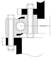
The suggested minimum thickness of the supporting material is tabulated below. The width of the supporting flanges must at least equal the width of the ring it supports. Thick circular supports are preferred over thinner supports with reinforcement ribs. With modern FEA analysis these figures can probably be reduced.
| Raceway Ø (mm) | 500 | 750 | 1000 | 1250 | 1500 | 2000 | 2500 | 3000 |
| Minimum thickness (mm) | 25 | 30 | 35 | 40 | 50 | 60 | 70 | 80 |
Flatness defects under load must not exceed the values indicated below to avoid tight spots or seizure; both of which will reduce the life of the ring. These values are for “long waves” around the circumference. Shorter wave defects (e.g. between 2 bolt holes) must not exceed ¼ of these values.
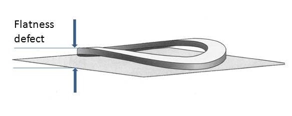
| Raceway Ø (mm) / Allowable defect (mm) | 500 | 750 | 1000 | 1250 | 1500 | 2000 | 2500 | 3000 |
| Single row ball brg | 0.12 | 0.18 | 0.21 | 0.25 | 0.28 | 0.336 | 0.38 | 0.42 |
| SIngle row x-roller or 2-row ball | 0.10 | 0.12 | 0.15 | 0.18 | 0.20 | 0.25 | 0.29 | 0.32 |
Defects in the radial direction (sometimes referred to as “conicity”) must not exceed 0.05mm /m based on the raceway diameter. If the above tolerances cannot be met, epoxy resins such as CHOCKFAST ORANGE may be used.
SLEW RING ORIENTATION
The filling plugs are positioned at the raceway hardening junctions. When fitting, the filling plugs must be positioned at the point of minimum strain (usually at right angles to the main load axis). In some cases the bolt pattern will by asymmetric to force this orientation.
DOWEL PINS OR SPIGOTS
In the event of high radial loads, or if a slew ring is used with a horizontal axis of rotation the circularity of the slewing ring may be affected. If circularity cannot be maintained by use of a structural adhesive (e.g. LOCTITE 586 or similar), the machined diameters on the bearing rings must be used. If this is impossible then a system of dowel pins should be considered.
FASTENING BOLTS
Although some manufacturers specify Grade 8.8 bolts, QCB® slewing rings are usually designed to be used with Grade 10.9 hexagon head or cap screw bolts. Check you have the correct grade of bolt available. For bearings in “CC” steel (50Mn) the use of flat hardened washers is recommended to reduce surface pressures under the bolt head and nut. If cap screws are used the specific pressure under the bolt head should not exceed the limits of the material. The use of any elastic (spring washers or Bellville washers) or serrated washers is prohibited and will negate the warranty.
Untreated bolts should be lightly oiled and tightened progressively using either a calibrated torque wrench or a hydraulic system, moving around the periphery of the slewing ring in 120 degree steps. The recommended bolt torque figures are tabulated below.
Large diameter bolts should be tightened hydraulically.
Ensure that the slew ring rotation is tested during the tightening process (if possible) as any “tight points” will become evident and prompt immediate investigation. The bolt torque figures should be checked again before the machine enters service as a degree of “settling” may occur, then after 100 hours of operation, and thereafter at least on an annual basis
| Strength class to DIN/ISO 898 | Grade 8.8 | Grade 10.9 | Grade 12.9 | |||||
| Yield point Rp 0,2 (Nmm-2) | 640 for <= M16 | 940 | 1100 | |||||
| 660 for >M16 | ||||||||
| ISO thread DIN 13 | Stress x-section area As (mm2) | Core x-section area A3 (mm2) | Tension force (kN) | Tightening torque(Nm) | Tension force (kN) | Tightening torque(Nm) | Tension force (kN) | Tightening torque(Nm) |
| M12 | 84.3 | 76.2 | 38.5 | 78 | 56 | 117 | 66 | 135 |
| M14 | 115 | 105 | 53 | 126 | 77 | 184 | 90 | 216 |
| M16 | 157 | 144 | 72 | 193 | 106 | 279 | 124 | 333 |
| M18 | 193 | 175 | 92 | 270 | 129 | 387 | 151 | 459 |
| M20 | 245 | 225 | 117 | 387 | 166 | 558 | 194 | 648 |
| M22 | 303 | 282 | 146 | 522 | 208 | 747 | 243 | 873 |
| M24 | 353 | 324 | 168 | 666 | 239 | 954 | 280 | 1116 |
| M27 | 459 | 427 | 221 | 990 | 315 | 1395 | 370 | 1665 |
| M30 | 561 | 519 | 270 | 1350 | 385 | 1890 | 450 | 2250 |
| M33 | 694 | 547 | 335 | To be determined by bolt elongation measurement | 480 | To be determined by bolt elongation measurement | 560 | To be determined by bolt elongation measurement |
| M36 | 817 | 759 | 395 | 560 | 660 | |||
| M39 | 976 | 913 | 475 | 670 | 790 | |||
| M42 | 1120 | 1045 | 542 | 772 | 904 | |||
| M45 | 1300 | 1224 | 635 | 905 | 1059 | |||
| M48 | 1470 | 1377 | 714 | 1018 | 1191 | |||
| M52 | 1760 | 1652 | 857 | 1221 | 1429 | |||
| M56 | 2030 | 1905 | 989 | 1408 | 1648 | |||
| M60 | 2360 | 2227 | 1156 | 1647 | 1927 | |||
SEALS
QCB® slew rings are fitted with a nitrile or NBR rubber lip seal which rides on the surface of the adjacent ring. In some high temperature units this is replaced with a VITON lip seal.
Special seal arrangements will be proposed if required. These include:
- Double seals
- V-ring seals
- Quad section seals
- Metal shields
- Offshore seals
Seals require annual inspection and possibly replacement if they are exposed.
GEARING
Metric slew rings generally have a 200 involute spur gear, although helical gears exist. Imperial bearings can use either a Fellowes Stub gear or an American stub or full depth gear.
As many slewing rings exhibit an addendum correction it is imperative to get a suitably corrected pinion to ensure efficient meshing. Our technical staff utilise the most up to date calculation software available in the design process.
From 2015 all geared QCB slewing rings are made in 42CrMo4 V steel to offer superior gear strength in comparison to some opposition products.
Pinion backlash must be set at the point of maximum eccentricity on the slew ring which will be marked, usually by 3 painted teeth.
Ensure each pinion is properly aligned to the gear with good contact maintained over the full face width.
A minimum clearance of between 0.03 – 0.05 x module is recommended under normal circumstances.
| Gear Mod | Backlash (mm) | Gear Mod | Backlash (mm) | Gear Mod | Backlash (mm) |
| 4 | 0.12 - 0.16 | 10 | 0.30 - 0.40 | 18 | 0.54 - 0.72 |
| 5 | 0.15 - 0.20 | 12 | 0.36 - 0.48 | 20 | 0.60 - 0.80 |
| 6 | 0.18 - 0.24 | 14 | 0.42 - 0.56 | 22 | 0.66 - 0.88 |
| 8 | 0.24 - 0.32 | 16 | 0.48 - 0.64 | 24 | 0.72 - 0.96 |
During installation the slewing rings should be rotated a few times to check the gear mesh.
OPERATIONAL CLEARANCE AND WEAR
After assembly the clearance or total deflection of the slewing ring under known test conditions should be determined to serve as reference data for future clearance checks to determine the amount of wear in the bearing.
The degree of “tilt” in the bearing can be measured, or the relative axial and radial movement of the rings using dial gauges. An average of at least 4 measurements around the circumference should be recorded.
Measurements should be taken as close to the raceways as possible to minimise the effects of elastic deflections in the structure. The measurement points should be marked so that the test can be recreated.
In general, slewing rings will wear at a linear rate in service. Once this rate of wear accelerates it is nearing the end of its service life.
Typical allowable wear figures for normal applications are tabulated below:-
For single and double row ball bearings
| Raceway Ø | Ball diameter (mm) | ||||
| mm | 20 | 25 | 30 | 35 | 40 |
| 1000 | 1.4 | 1.4 | 1.5 | 1.7 | 1.9 |
| 1250 | 1.6 | 1.6 | 1.7 | 2.0 | |
| 1500 | 1.6 | 1.7 | 1.7 | 2.0 | |
| 1750 | 1.8 | 1.8 | 2.1 | ||
| 2000 | 1.9 | 2.2 | |||
| 2250 | 2.0 | 2.3 | |||
| 2500 | 2.0 | 2.3 |
For single row x-roller bearings
| Raceway Ø | Roller diameter (mm) | ||||
| mm | 16 | 20 | 25 | 32 | 40 |
| 400 | 0.22 | 0.22 | 0.24 | ||
| 800 | 0.25 | 0.27 | 0.29 | 0.33 | 0.38 |
| 1000 | 0.30 | 0.32 | 0.34 | 0.38 | 0.43 |
| 1500 | 0.50 | 0.52 | 0.54 | 0.58 | 0.63 |
| 2000 | 0.62 | 0.64 | 0.68 | 0.73 | |
| 2500 | 0.74 | 0.78 | 0.83 |
These figures do not apply to safety critical applications (e.g. amusement rides).
As a “rule of thumb”, once the measured deflection exceeds 1.5x the initial figure, plans for the replacement of the slew ring should be made – considering that they are sometimes long lead items. If the measured deflection exceeds 2x the initial clearance then the ring should be replaced immediately for safety reasons.
RACEWAY LUBRICATION
QCB® slewing rings are assembled using a standard NLGI class 2 mineral oil based EP grease. The degree of fill can vary and it is imperative that customers grease any slewing ring during installation. The raceways can be adequately lubricated by any good quality standard lithium based EP2 bearing grease.
The regreasing interval is best determined by the environment, and is mandatory after a long period of storage. In aggressive environments it must be recognised that the grease acts as a barrier to contamination.
| Environmental conditions | Recommended relubrication interval |
| Workshop/ Dry & clean | ~ 300 hours of operation or every 6 months |
| Outside / Exposed | ~ 100 - 200 hours of operation or every 4 months |
| Aggressive environment | ~ 50 hours of operation or every 2 months |
| Extreme conditions | ~ Continuous lubrication system preferred |
During regreasing it is advisable to rotate the bearing to ensure distribution of the fresh grease as well as to avoid over pressurising the seals as this may force them out of their grooves.
As most slew rings rotate slowly, they can operate 100% full of grease. Ideally a thin smear of fresh grease should start to weep from under the lip seals. A simple formula helps to determine the approximate amount of grease required in grams (all dimensions in mm)
- Single row ball brg Grease qty (gr) = 0.7 x Raceway f x ball f 2 / 1000
- Single row roller brg Grease qty (gr) = 0.5 x Raceway f x roller f 2 / 1000
See our range of GreaseMax lubricators
GEAR LUBRICATION
The gear should be lubricated immediately after assembly and setting of the backlash. Suitable open gear grease should be brushed or sprayed on to cover the teeth completely.
Download the QCB Slewing ring Installation & Maintenance Guide from our DOWNLOADS page
Load combination and graphical analysis
Slewing rings are designed to handle axial, radial and moment loads in combination. But the load curves published are 2 dimensional and it is therefore necessary to combine the axial load Fa with the radial load Fr into a single equivalent load P in order to plot an operating point.
- For all light series bearings, (FUN/FEG/FIG 20 and SUN/SEG/SIG 20 & X14 Series) the relevant formula is P = Fa + 3.225 Fr
- For other slewing rings the factor used depends on the ratio of Fa to Fr
However, interpretation of the results requires experience.
QCB design software looks at the stresses generated under the most heavily loaded roller and is a more accurate way of assessing slewing ring life. As well as the raceway we look a the bolt strength as well as the gearing.
Call us! Our advice is freely and gladly given. Consult QCB Technical by submitting your design requirements to NBC Technical using the Design Data Form . Send the design requirements as well as a sketch. cad file or 3D model to our technical team email. (DWG/ DXF/ STP files etc)