SIG X14 x-roller metric series
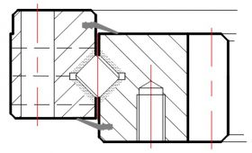
Two solid section rings separated by 14mm crossed rollers, with the inner ring being geared. This series has a constant height of 56mm, and a standard range of external diameters ranging from 486mm to 1166mm.
- Overview
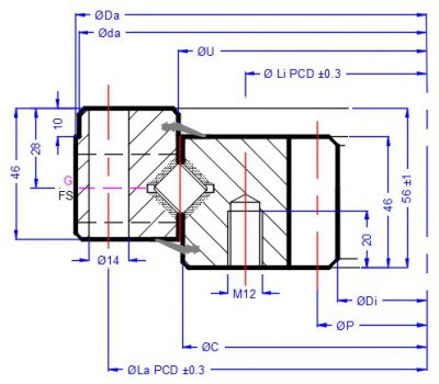
- Dimensions
- Technical
- Downloads
All QCB® slewing rings are manufactured to the highest possible quality levels in ISO certified factories. A QCB® Quality Standard defines all aspects of their dimensions and tolerances as well as all aspects of manufacturing from materials properties, all stages of production, as well as packing and labelling.
Whilst the data on the site is updated regularly, we reserve the right to implement subtle changes to these standards in our quest for continual product improvement.
Applications
- Industrial positioners (e.g. welding assemblies and jigs)
- Ship or truck loading chutes and swivels
- Stretch wrapping machines
- Conveyors and other materials handling equipment
- Simple amusement rides
Need help?
Our technical team have many years of experience and are happy to assist with selection. Call or e-mail them for fast, efficient and professional advice.
The Design Form will assist you in defining your application details.
| QCB Reference | Outline dimensions & weight | |||||||
| Da | Di | U | C | da f9 | di H9 | Load curve | Weight | |
| mm | mm | mm | mm | mm | mm | kg | ||
| SIG 486 X14 01 AA LM | 486 | 324 | 415.5 | 412.5 | 484 | 1 | 31 | |
| SIG 616 X14 01 AA LM | 616 | 444 | 545.5 | 542.5 | 614 | 2 | 42 | |
| SIG 716 X14 01 AA LM | 716 | 546 | 645.5 | 642.5 | 714 | 3 | 50 | |
| SIG 816 X14 01 AA LM | 816 | 648 | 745.5 | 742.5 | 814 | 4 | 58 | |
| SIG 916 X14 01 AA LM | 916 | 736 | 845.5 | 842.5 | 914 | 5 | 69 | |
| SIG 1016 X14 01 AA LM | 1016 | 840 | 945.5 | 942.5 | 1014 | 6 | 76 | |
| SIG 1166 X14 01 AA LM | 1166 | 984 | 1095.5 | 1092.5 | 1164 | 7 | 91 | |
| QCB Reference | Outer holes | Inner holes | 20o spur gear | |||||
| La | na | Li | ni | P | m | z | Fz MAX | |
| mm | mm | mm | KN | |||||
| SIG 486 X14 01 AA LM | 460 | 24 | 375 | 24 | 335 | 5 | 67 | 34 |
| SIG 616 X14 01 AA LM | 590 | 32 | 505 | 32 | 456 | 6 | 76 | 41 |
| SIG 716 X14 01 AA LM | 690 | 36 | 605 | 36 | 558 | 6 | 93 | 41 |
| SIG 816 X14 01 AA LM | 790 | 40 | 705 | 40 | 660 | 6 | 110 | 41 |
| SIG 916 X14 01 AA LM | 890 | 40 | 805 | 40 | 752 | 8 | 94 | 55 |
| SIG 1016 X14 01 AA LM | 990 | 44 | 905 | 44 | 856 | 8 | 107 | 55 |
| SIG 1166 X14 01 AA LM | 1140 | 48 | 1055 | 48 | 1000 | 8 | 125 | 55 |
| Standard grease fitting | # at least 2x M8 on outer ring | |||||||
Custom designs
- Double drilled or custom drilling patterns
- Higher precision bearings with location diameters
- Reduced internal clearance (Class 5 & Class 6)
- Black oxide or zinc plating for enhanced corrosion protection
- Epoxy paint or even Nylon coated units to special order
- Stainless steel or aluminium versions
Materials
From 2015 all SIGX14 Series slewing rings will be manufactured in 42CrMo4 steel. Smaller units are usually produced in 50Mn / C45.
Internal construction
Standard SIGX14 Series bearings incorporate plastic spacers, but ball spacers, steel or brass spacers, or even full complement and caged designs can be supplied for specific applications.
Seals
A land riding NBR (nitrile rubber) seal strip is standard. VITON seals can be supplied to order.
Gearing
The SIGX14 Metric series has a standard 20° pressure angle, uncorrected spur gear cut into the inner ring.
Lubrication
QCB® Slewing rings are assembled with a small quantity of Lithium EP2 grease. It is important that all slewing rings are greased during installation and prior to operation. SIGX14 series slewing rings will usually have 4 or 6 grease nipples DIN 71412 M8x1 on the radial face of the outer ring. Sufficient grease nipples for all holes as well as Nylon plugs (to insert if a grease nipple is not required) are supplied with each ring.
Special greases can be supplied on demand as can GreaseMax Automatic Lubricators and Accessories.
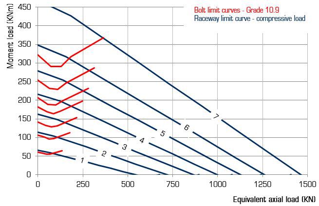
Load & Bolt limit curves
If both a radial and an axial load act on the bearing these must be combines into a single equivalent load to enable basic selection from the load curves. The raceway limit is illustrated by the blue line, the red line illustrates the limit for the specified number of Grade 10.9 bolts.The load point should be well under the relevant load curve for long life.
Grade 8.8 bolts can be used but only after approval by our technical team.
Similarly if the load is suspended or the axis of rotation is not vertical please refer the application details to us and take advantage of our decades of experience!
| QCB reference | PDF Print | CAD.dwg | MODEL.STP |
| SIG 486 X14 01 AA LM | SIG 486 X14.pdf | SIG 486 X14.dwg | SIG 486 X14.STP |
| SIG 616 X14 01 AA LM | SIG 616 X14.pdf | SIG 616 X14.dwg | SIG 616 X14.STP |
SIG 716 X14 01 AA LM | SIG 716 X14.pdf | SIG 716 X14.dwg | SIG 716 X14.STP |
| SIG 816 X14 01 AA LM | SIG 816 X14.pdf | SIG 816 X14.dwg | SIG 816 X14.STP |
| SIG 916 X14 01 AA LM | SIG 916 X14.pdf | SIG 916 X14.dwg | SIG 916 X14.STP |
| SIG 1016 X14 01 AA LM | SIG 1016 X14.pdf | SIG 1016 X14.dwg | SIG 1016 X14.STP |
| SIG 1166 X14 01 AA LM | SIG 1166 X14.pdf | SIG 1166 X14.dwg | SIG 1166 X14.STP |