


Product Catalogue
Find Out More
Product Catalogue
Find Out More
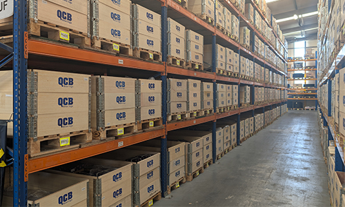


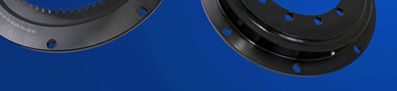
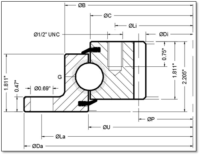
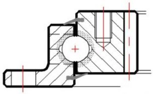
FIG 20 Imperial Series (RK6-N)
A flange profile outer and a geared inner ring separated by a 3/4″ ball set; a constant section height of 2.025″ and a standard range of external diameters ranging from 20.39″ to 47.17″ matching American dimension, gearing and bolt patterns.
Compared with traditional combination bearing and gearing systems, slewing rings provide a sealed bearing to accommodate axial, radial and moment loads while simultaneously providing a gear for power trasmission as well as bolt holes for fixation.
Key Features
- A reduction in the number of design elements
- Less component machining
- Quick and easy assembly of machinery
- Weight savings
Our engineers design, manufacture, and supply components to your exact specification. Contact us to discuss your project.
A flange profile outer and a geared inner ring separated by a 3/4″ ball set; a constant section height of 2.025″ and a standard range of external diameters ranging from 20.39″ to 47.17″ matching American dimensions, gearing and bolt patterns.
All QCB® slewing rings are manufactured to the highest possible quality levels in ISO-certified factories.
A QCB® quality standard defines all aspects of their dimensions and tolerances as well as all aspects of manufacturing, from material properties and all stages of production to packing and labelling.
Applications While a flange reduces the overall weight of the bearing, it also reduces its torsional rigidity, and these bearings are thus best suited to light- or medium-duty applications where there is not a high load eccentricity.
If the IMPERIAL sizes and bolt patterns are not quite right, consider the FIG20 Metric series
What are the Typical Uses for Slewing Rings?
- Cranes and crane handling systems
- Man lifts and access platforms
- Bottling and packing line carousels
- Robotics and positioning systems
- Solar tracking systems
- Wind turbines
- Winches
- Water treatment plants
- Machine tools
| QCB reference | Outline dimensions & weight | |||||||
| Da | Di | B | U | C | Load curve | Weight | ||
| in | in | in | in | in | lbs | |||
| FIG 518 20 61 AA LM | 20.390 | 12.850 | 17.870 | 16.220 | 16.140 | 1 | 65 | |
| FIG 648 20 61 AA LM | 25.510 | 17.600 | 22.990 | 21.340 | 21.260 | 2 | 90 | |
| FIG 748 20 61 AA LM | 29.450 | 21.600 | 26.930 | 25.280 | 25.200 | 3 | 106 | |
| FIG 848 20 61 AA LM | 33.390 | 25.600 | 30.870 | 29.220 | 29.140 | 4 | 121 | |
| FIG 948 20 61 AA LM | 37.320 | 29.133 | 34.800 | 33.150 | 33.070 | 5 | 148 | |
| FIG 1048 20 61 AA LM | 41.260 | 33.133 | 38.740 | 37.090 | 37.010 | 6 | 165 | |
| FIG 1198 20 61 AA LM | 47.170 | 39.133 | 44.650 | 43.000 | 42.920 | 7 | 188 | |
| QCB reference | Outer holes | Inner holes | 20o spur gear | |||||
| La | na | Li | ni | P | DP | z | Fz MAX | |
| in | lb.f | |||||||
| FIG 518 20 61 AA LM | 19.250 | 8 | 14.880 | 12 | 13.250 | 4 | 53 | 7883 |
| FIG 648 20 61 AA LM | 24.380 | 10 | 19.630 | 15 | 18.000 | 4 | 72 | 7883 |
| FIG 748 20 61 AA LM | 28.380 | 12 | 23.630 | 18 | 22.000 | 4 | 88 | 7883 |
| FIG 848 20 61 AA LM | 32.250 | 15 | 27.630 | 18 | 26.000 | 4 | 104 | 7883 |
| FIG 948 20 61 AA LM | 36.250 | 18 | 31.500 | 18 | 29.667 | 3 | 89 | 10500 |
| FIG 1048 20 61 AA LM | 40.130 | 18 | 35.500 | 20 | 33.667 | 3 | 101 | 10500 |
| FIG 1198 20 61 AA LM | 46.000 | 18 | 41.500 | 24 | 39.667 | 3 | 119 | 10500 |
| Standard grease fitting | # at least 2x 1/4″-28 UNF 2B on outer ring | |||||||
Interchange information
The FIG20 Imperial Series is interchangeable with bearings from other manufacturers such as Rotek, Kaydon, AVON, Silverthin . However there may be variations to this rule (e.g. OEM variants) and we invite you to refer to our technical staff for assistance.
| FIG 518 20 61 AA LM | RK6-16N1Z | L6-16N9Z | SK6 16 NZ | 716 MB1 | |||
| FIG 648 20 61 AA LM | RK6-22N1Z | L6-22N9Z | SK6 22 NZ | 721 MB1 | |||
| FIG 748 20 61 AA LM | RK6-25N1Z | L6-25N9Z | SK6 25 NZ | 725 MB1 | |||
| FIG 848 20 61 AA LM | RK6-29N1Z | L6-29N9Z | SK6 29 NZ | 729 MB1 | |||
| FIG 948 20 61 AA LM | RK6-33N1Z | L6-33N9Z | SK6 33 NZ | 733 MB1 | |||
| FIG 1048 20 61 AA LM | RK6-37N1Z | L6-37N9Z | SK6 37 NZ | 737 MB1 | |||
| FIG 1198 20 61 AA LM | RK6-43N1Z | L6-43N9Z | SK6 43 NZ | 742 MB1 | |||
Custom designs
- Double drilled or custom drilling patterns
- Higher precision bearings with location diameters
- Reduced internal clearance (Class 5 & Class 6)
- Black oxide or zinc plating for enhanced corrosion protection
- Epoxy paint or even Nylon coated units to special order
- Stainless steel or aluminium versions
Materials
All geared slewing rings are manufactured in 42CrMo4 V steel to offer superior gear strength over some other brands.
Internal construction
Standard FIG20 Imperial Series bearings incorporate plastic spacers, but ball spacers, steel or brass spacers, or even full complement and caged designs can be supplied for specific applications.
Seals
A land riding NBR (nitrile rubber) seal strip is standard. VITON seals can be supplied to order.
Gearing
The FIG20 Imperial Series has a standard 20° pressure angle, uncorrected spur gear cut into the inner ring.
Lubrication
QCB® Slewing rings are assembled with a small quantity of Lithium EP2 grease. It is important that all slewing rings are greased during installation and prior to operation. FIG20 Imperial Series slewing rings will usually have 4 or 6 grease nipples DIN 71412 M8x1 on the radial face of each ring. Sufficient grease nipples for all holes as well as Nylon plugs (to insert if a grease nipple is not required) are supplied with each ring.
Special greases can be supplied on demand as can GreaseMax Automatic Lubricators and Accessories.
Load & Bolt limit curves
If both a radial and an axial load act on the bearing these must be combines into a single equivalent load to enable basic selection from the load curves. The raceway limit is illustrated by the blue line, the red line illustrates the limit for the specified number of Grade 10.9 bolts.The load point should be well under the relevant load curve for long life.
Grade 8.8 bolts can be used but only after approval by our technical team.
Similarly if the load is suspended or the axis of rotation is not vertical please refer the application details to us and take advantage of our decades of experience!
Need additional support?
While this site provides the CAD drawings to download, our dedicated QCB slewing ring website offers a wider range of technical information and resources, including:
- STP Files
- Load Curves
- CAD Prints
Our experienced technical team has many years of industry expertise and is available to help you select the most suitable solution for your application.
For fast, efficient, and professional advice, please contact us by phone or email
For any enquiries regarding FIG 20 Imperial Series (RK6-N), please complete our enquiry form, and a member of our technical team will respond promptly. Alternatively, you can reach out directly to one of our offices using the contact details here. Our specialists are ready to provide guidance and support tailored to your machinery and engineering needs.